Company News
Syringe Filling Machine: Choosing Pump Type, Fill Accuracy and Stopper Handling
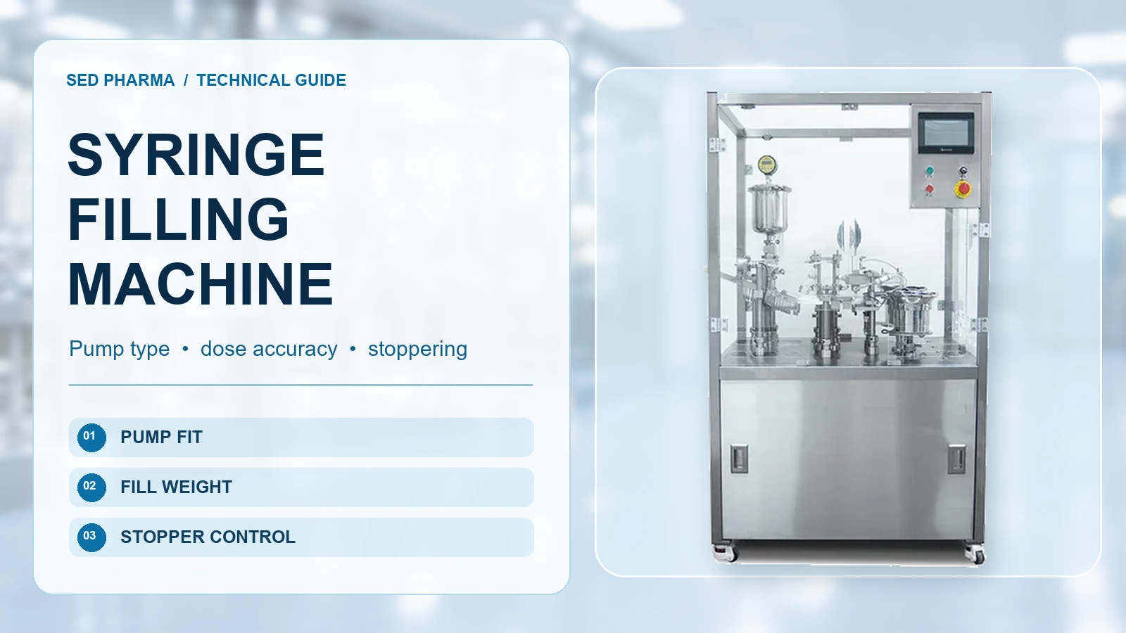
A syringe filling machine should be specified around the actual dose, formulation, syringe-and-stopper combination, and required good output—not around a catalog speed alone. Choose a pump by testing the product at the smallest and largest intended fills; set fill-weight limits using the approved dose specification and measured product density; then challenge stopper placement, bubbles, and container-closure integrity at production speed. For an aseptically filled prefilled syringe, the filling station is only one part of the validated sterile process. The user requirements specification (URS) must also define the target market's GMP framework, component preparation, environmental protection, interventions, and acceptance evidence.
Define the syringe-format requirements first
Start with a format matrix for every barrel size and material, nest or bulk presentation, flange and tip geometry, presterilization state, stopper design, lubricant or silicone system, target fill, headspace, and required delivered dose. Record the viscosity range at filling temperature, foaming or shear sensitivity, particulate or suspension behavior, and compatibility of every product-contact material. A nominal syringe capacity does not establish the usable fill or the delivered dose. The barrel, tip, stopper, and delivery accessory form a system; FDA's 2013 draft technical supplement discusses why dimensional conformity alone may not establish connection and delivery performance. The draft is nonbinding and marked “not for implementation,” so it is a technical reference rather than a current GMP requirement.
For each configuration, define an approved target mass or volume, acceptable individual-unit range, in-process action limits, and the measurement method. If the release claim is a volume, convert gravimetric results with product density measured at the relevant temperature, and state whether the target is filled volume, extractable volume, or delivered volume. These are not interchangeable. The specified fill must account for product retained in the tip and delivery path without inventing an allowance from a machine specification. Before equipment selection, identify whether the process is aseptic filling of a sterile product or another validated route; that decision controls the environmental and sterilization requirements.
Choose the pump by product behavior and changeover strategy
Ceramic or rotary-valve piston dosing
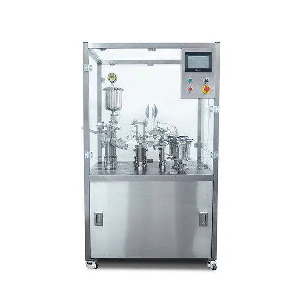
A piston-based system meters a defined displacement and can suit aqueous or more viscous products when the wetted path, valves, and seals are compatible. SED Pharma's ceramic-plunger syringe filling and vacuum-plugging system lists 0.5–20 mL syringe formats and gives ≤±1–2% filling accuracy and 1,200–1,800 pieces per hour as catalog figures. Treat these as catalog specifications to verify by trial, not as batch acceptance criteria. Confirm the proposed pump's actual stroke range, minimum reliable dose, product hold-up, cleaning and sterilization method, and whether dose changes require parts. Ask for product-contact drawings and a change-part list.
Peristaltic and other low-contact options
Peristaltic dosing confines product contact to tubing, which can simplify a single-use path and changeover. It may suit shear-sensitive products, but tubing material, size, compression history, backpressure, and calibration can affect delivered mass. A rolling-diaphragm or other low-shear option may be worth evaluating for sensitive biologics. Syntegon's filling-system overview describes these options as different application fits, not universal accuracy rankings. Evaluate pump candidates with the actual formulation, line speed, fill range, nozzle, tubing or seal set, and sterilization strategy. Do not assume that the cleanest changeover path is automatically the most accurate at the smallest dose.
For each candidate, run a matched trial at the lowest, nominal, and highest fill and at the intended sustained speed. Measure individual fills across every active head at startup, after stabilization, during the run, and after a planned stop. Record the head number, formulation temperature, density, pump settings, pressure, nozzle position, and rejected units. Separate systematic bias (mean against target) from precision (spread of individual fills). If the product can settle or change viscosity, include the relevant hold time and agitation condition; a stable fill weight may still conceal concentration variation in a suspension.
Include the nozzle and feed system in the pump trial. Bottom-up filling, nozzle withdrawal profile, and suck-back can reduce splashing or dripping for some liquids, but each adjustment can change the dispensed mass or introduce air. Verify the prime sequence, first-fill behavior after a pause, and whether partially filled or missing syringes are reliably rejected. For a multi-head system, define how an individual head is isolated and how its accepted units are traced when one channel fails. Record product loss in the manifold and tubing as part of changeover planning, especially for small, high-value batches.
Verify fill accuracy as a product-specific result
The basic gravimetric calculation is net fill mass = filled assembly mass − empty assembly mass, with a qualified tare method. When volume is the specified measurand, volume = net mass ÷ measured density. Apply the site's approved correction and uncertainty treatment to both terms. For example, a net mass of 0.998 g at a measured density of 0.998 g/mL corresponds to 1.000 mL; this arithmetic is illustrative, not a proposed tolerance. Use a calibrated balance with suitable resolution, define how residual exterior droplets and trapped air are handled, and preserve traceability from each sample to its filling head and time point.
Agree the acceptance standard before a factory or site test: number of units per head and interval, target and lower/upper individual limits, allowable mean bias and variability, response to a failed check, and the sampling plan's statistical rationale. State whether results include start-up, interventions, rejected units, and the last syringes after a stop. A product page's “filling accuracy” percentage may use a different denominator or test condition; it must not replace the approved dose requirement. For small doses, report absolute as well as percentage error so a seemingly modest percent does not hide a clinically meaningful volume difference. Where delivery performance matters, verify the assembled syringe and accessory under the product's intended use conditions; FDA's 2013 draft technical supplement recommends performance evidence on the final assembly. That draft recommendation is nonbinding and not a substitute for the applicable approved product requirements.
Specify stopper handling as part of dose and integrity control
Stopper feeding, orientation, insertion method, and final axial position affect headspace, bubbles, leakage, and the geometry of the delivered dose. Record stopper supplier and size, coating or siliconization, sterilization status, acceptable insertion-depth window, plunger movement, and maximum contact force. Compare vent-tube and vacuum insertion where appropriate, then challenge the chosen method with the actual stopper, barrel, fill volume, and viscosity. Even if vacuum insertion reduces visible bubbles, test liquid displacement, stopper tilt, damage, and headspace behavior and closure integrity under product-justified hold or transport conditions. Syntegon's syringe-line overview identifies stopper-position measurement and vent-tube or vacuum insertion as relevant in-process controls.
Define automatic detection and rejection for missing, inverted, high, low, or damaged stoppers and for syringes with visible bubbles or liquid on sealing surfaces. Verify reject segregation and reconciliation: a failed unit must not silently rejoin the good stream. The product manufacturer must select a container-closure integrity (CCI) method for the actual syringe-and-stopper system, establish method suitability, and approve a sampling plan that addresses storage and shipping risks; equipment performance data alone cannot guarantee sterile integrity. Visual inspection alone cannot establish microbial barrier integrity. The FDA aseptic-processing guidance addresses container-closure integrity as part of sterile-product assurance; Health Canada's Annex 1 guidance calls for validated closure methods and a scientifically justified integrity test plan for non-fusion closures.
Stopper position should be measured against a defined reference on the barrel, with tolerance and measurement uncertainty agreed before the trial. Check position immediately after insertion and after the approved hold or transport simulation, because movement may emerge later. Challenge the worst-case combination of minimum fill, maximum fill, highest viscosity, and component tolerance where justified by risk assessment. Document what happens when a stopper is not picked up, when vacuum is lost, and when a nest pocket is empty. The line should identify and segregate those units without operator interpretation or undocumented manual recovery.
Build the aseptic and integration requirements into the URS
For a sterile prefilled syringe, first name the target market and applicable GMP system—for example, US 21 CFR parts 210/211 with FDA aseptic-processing guidance, or EU GMP Annex 1. The site's contamination control strategy should then define the critical-zone protection and background classification for the selected RABS or isolator design. Neither a hood label nor a cleanroom class claimed on an equipment page establishes a compliant installation. Specify the sterile component entry route, nest or tub opening, stopper transfer, filling path, aseptic connections, pressure and airflow monitoring, environmental monitoring alert/action limits, and response to trends. The EU GMP Annex 1 and FDA guidance provide the basis for the site-specific program.
Add filtration or other sterilization strategy, pre- and post-use filter integrity checks where applicable, sterilized equipment and component hold times, sterile product hold time, maximum filling time, and permitted interventions. The aseptic process simulation (APS/media fill) should represent line speed, format changes, weight checks, normal and nonroutine interventions, stoppages, and the longest permitted run. These requirements belong in the equipment interface and acceptance matrix even when a supplier does not own the entire process. The FDA guidance explicitly includes weight checks, line speed, container closures, and interventions in media-fill design.
Confirm upstream and downstream handoffs: sterile syringe presentation, de-nesting or tray transport, no-syringe/no-fill logic, stopper supply, reject path, vision checks, labeling, and inspection. A line layout should show where each sterile boundary starts and ends. The liquid filling equipment family is the appropriate commercial landing page for comparing configurations; SED Pharma should review the exact barrel, dose, product, containment, and handoff requirements before proposing the scheduled machine. The broader oral-liquid equipment article explains common pump families, but syringe-specific stopper and delivered-dose controls here are additional decisions.
Data requirements matter as much as mechanics. The URS should identify user roles, recipe control, electronic record and audit-trail needs, calibration status, alarm limits, and how batch records associate a syringe lot, product lot, pump set, stopper lot, head, and time. Where an inline balance is proposed, define how challenge weights and rejected-unit records are verified. A machine's ability to display a number does not establish that the measurement is traceable, retained, or suitable for batch disposition.
Use a cause–test–action matrix during trials
| Observation | Possible cause to test | Confirmation test | Controlled action |
|---|---|---|---|
| Low or drifting net fill | Pump setting, tubing fatigue, air, backpressure, or viscosity change | Trend individual mass by head and time; check density, prime state, pressure, and product temperature | Recalibrate or replace qualified path components under change control; repeat the defined sample set |
| Large head-to-head spread | Unequal pump calibration, nozzle behavior, or feed imbalance | Compare each head at the same fill and speed; inspect nozzle and supply path | Correct the identified head or feed path and requalify all heads |
| Bubbles or variable headspace | Aeration, nozzle withdrawal, stopper insertion, or vacuum setting | Record bubble rate and stopper position at each setting; inspect during and after the hold | Adjust one validated setting at a time; repeat integrity and dose checks |
| High or tilted stopper | Stopper feed orientation, insertion force, barrel variation | Measure axial position and inspect orientation by format and station | Correct feed tooling or insertion profile, then challenge worst-case formats |
| Leaks after handling | Closure mismatch, stopper damage, tip defect, or transport stress | Use a validated integrity method on statistically justified samples, including stressed units | Quarantine affected population; investigate components and revalidate closure process |
Investigate in order: confirm the measurement method and material state; isolate whether the defect follows a fill head, syringe format, time, or intervention; change one controlled variable; then repeat the same sampling plan. Do not use a good average to mask out-of-limit individual syringes. Read the site's liquid-filling fault guide for generic mechanical checks; syringe stopper and sterile-boundary failures require the additional tests above.
Write an acceptance protocol before selecting the machine
Define a production-representative continuous run duration, stabilization period, approved fill range, syringe and stopper lots, formulation or qualified surrogate, and every permitted planned stop. Before the run, set the maximum unplanned downtime, maximum reject fraction, and the denominator for good output (filled units, inspected units, or released acceptable units). Record start-up scrap, weight-check samples, intervention rejects, stopper rejects, and closure failures separately. A simple example is 30 minutes of setup followed by four continuous hours at the agreed rate; the site's quality and validation teams must approve the actual duration and limits. Name the maximum allowed recovery time after a stop and include post-restart sampling.
For fill verification, specify a justified number of individual syringes per head at start, each interval, after each intervention, and end; use the same plan at minimum and maximum planned doses. Define net-mass method, density measurement, balance calibration, individual and mean limits, and action on one failure. For stopper handling, specify 100% online position detection if that is the agreed design, challenge the reject mechanism with known faults, and separately test closure integrity by a product-owner-approved method with a justified sample size. Acceptance must also cover bubbles, particles, component damage, data capture, alarm records, environmental-monitoring response, sterilization or filtration controls, and APS evidence according to the site's GMP framework. An equipment FAT can demonstrate mechanical functions and sampled performance; it cannot by itself validate the entire aseptic process at the manufacturing site.
Convert the URS into a supplier deliverables matrix. State which tests occur at factory acceptance (FAT) with a qualified surrogate and which must be repeated at site acceptance (SAT) with installed utilities, sterile interfaces, and actual line handoffs. Require a URS-to-test traceability matrix, signed FAT/SAT protocols and deviation records, as-built product-contact and utility drawings, a change-part list by syringe and stopper format, and current calibration certificates for critical balances, pressure and vacuum gauges, temperature sensors, and other instruments used in acceptance. Specify the supplier's installation qualification/operational qualification (IQ/OQ) support package, including manuals, component certificates where applicable, software version and backup records, and executed tests for recipes, user access, alarms, audit trails, data export, and rejection logic. Allocate ownership of process qualification, APS, CCI method suitability, and batch release to the product manufacturer in the contract; do not imply the machine FAT covers these site responsibilities.
The decision is complete only when the proposed pump, nozzle, syringe transport, stopper system, and sterile interfaces meet the same product-specific test.
SED Pharma can use its ceramic-plunger syringe filling system as one configuration reference, while the production-line planning article provides broader layout context. Send the team your syringe and stopper drawings, smallest and largest dose, density and viscosity range, formulation risks, target good units per shift, GMP market, aseptic boundary, and proposed acceptance limits.
Submit those requirements through the project inquiry for a focused technical review.