Company News
How Do You Select a Lyophilizer Vacuum Pump and Verify Its Performance?
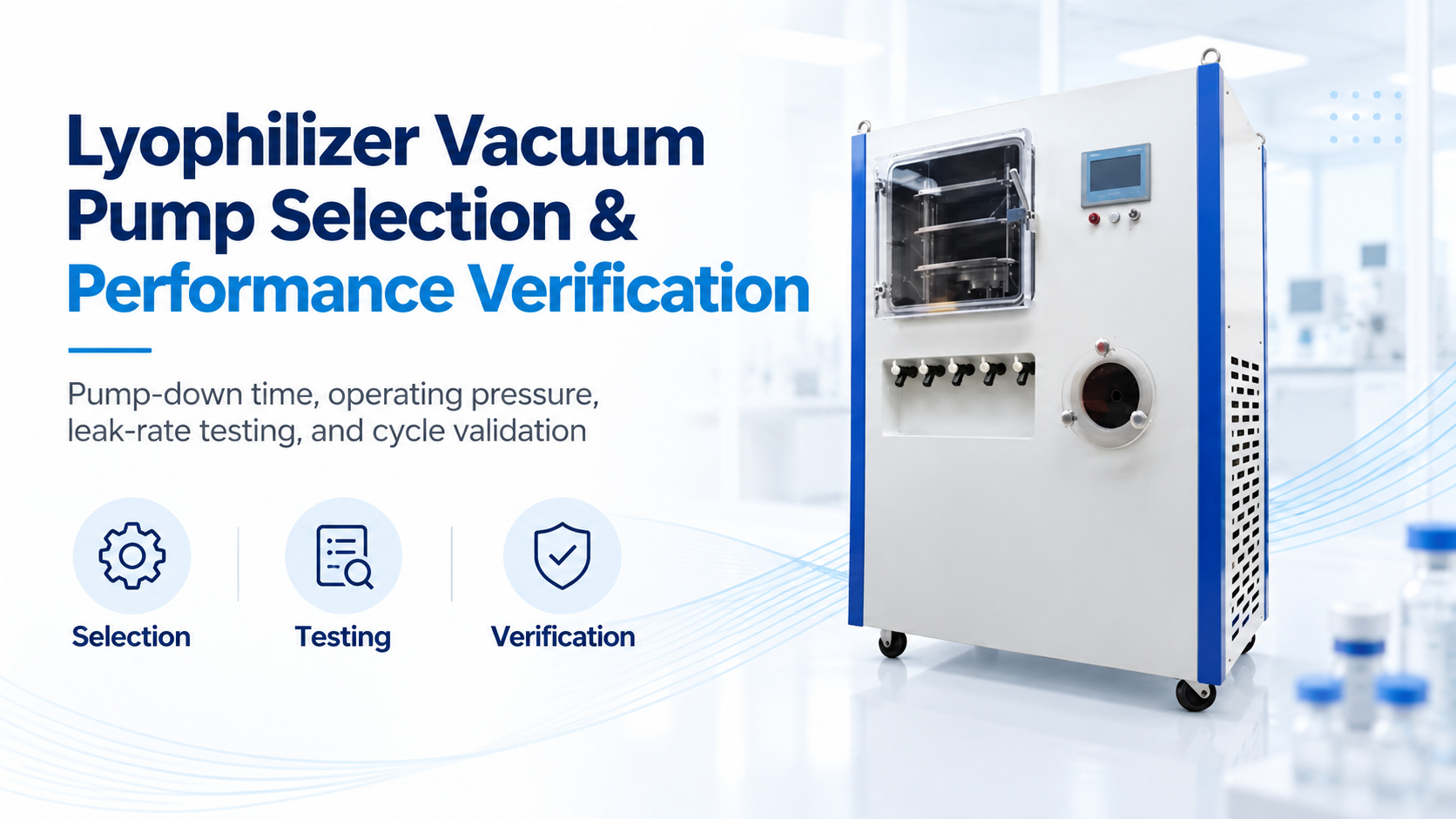
Selecting a vacuum pump for a pharmaceutical lyophilizer is not a nameplate-sizing exercise. The pump, chamber, condenser, piping, valves, vapor load, control sequence, and pressure instruments form one vacuum system. A pump can meet its catalog ultimate pressure and still fail to deliver the required chamber pump-down or stable process pressure after conductance losses, vapor loading, or contamination are considered.
Why selection starts with the complete lyophilizer
During primary drying, most water vapor should be captured by the condenser before it reaches the pump. The vacuum system must still remove non-condensable gas, leakage, desorbed gas, and vapor that passes the condenser. Selection therefore starts with the chamber volume, condenser capacity and temperature, expected vapor and gas loads, target pressure range, allowable pump-down time, piping geometry, cleaning strategy, and product-containment requirements.
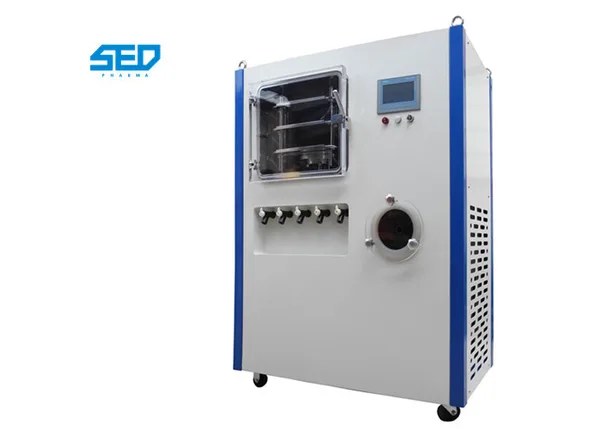
Compare pump types against the process risk
Oil-sealed rotary-vane pumps
Oil-sealed rotary-vane pumps are widely used because they can provide deep vacuum with a compact footprint. The assessment must address oil condition, gas-ballast use, backstreaming controls, exhaust treatment, condensate exposure, and maintenance access. Vapor or solvent contamination can degrade oil and reduce attainable pressure.
Dry primary pumps
Dry scroll, screw, or claw pumps avoid process-contact oil in the pumping chamber. They may reduce oil-contamination concerns, but material compatibility, purge requirements, temperature, particulate sensitivity, maintenance method, noise, and achievable performance under the actual gas load still require evaluation.
Primary pump with a booster
A roots-type booster can increase effective pumping speed over part of the pressure range. Its engagement pressure, bypass or protection logic, thermal limits, and compatibility with the primary pump must be specified as a system rather than as an independent component.
Write the selection basis into the URS
The user requirement specification should define the usable pressure range, maximum pump-down time, chamber volume, clean and dry test condition, representative load condition, condenser operating state, leakage limit, utilities, materials of construction, allowable contamination, exhaust handling, redundancy, maintainability, instrumentation, alarms, data capture, and qualification deliverables.
A first screening estimate for required effective pumping speed is:
S = V/t × ln(P1/P2)
where S is effective pumping speed at the chamber, V is chamber volume, t is pump-down time, and P1 and P2 are initial and final absolute pressures. This idealized equation is only a screening calculation. It does not include leakage, desorption, vapor load, condenser performance, or the pressure-dependent pump-speed curve.
Account for inlet conductance and measurement location
Long or narrow pipework, bends, filters, traps, valves, flexible hoses, and partially open components reduce conductance. Consequently, chamber pumping speed is lower than the pump's rated inlet speed. Compare pressure at the chamber and near the pump inlet during testing, and locate the control gauge where it represents the process requirement. Gauge type, range, calibration, temperature sensitivity, and exposure to condensable vapor all affect the result.
Set acceptance criteria before buying the pump
Define measurable criteria for clean, dry, empty pump-down; attainable pressure; pressure stability; isolation pressure rise or leak rate; loaded-cycle performance; condenser operating conditions; noise and temperature; recovery after gas ballast or purge; alarm response; and repeatability. A single ultimate-vacuum value is not enough.
Contamination and aseptic-boundary risks must also be documented. Review oil backstreaming, pump exhaust, product or cleaning-agent carryover, drain paths, filters, seals, and maintenance interventions. The design and qualification strategy should follow the site's contamination-control, occupational-safety, and change-control requirements.
How to verify and qualify the installed vacuum system
Installation qualification
Verify the approved pump and accessories, materials, piping orientation, valve direction, utilities, exhaust route, instruments, calibration status, documentation, lubrication or purge requirements, and maintenance access.
Operational qualification
Challenge pump-down, attainable pressure, pressure control, leak or isolation pressure rise, alarms, interlocks, booster sequencing, condenser conditions, and defined failure responses using approved instruments and test conditions.
Performance qualification and lifecycle monitoring
Demonstrate repeatable performance with representative loads and approved cycles. Trend pump-down time, chamber and inlet pressure, condenser temperature, leak-test results, motor current, pump temperature, oil or consumable condition, alarms, and maintenance history. Establish alert and action limits from qualified performance rather than waiting for a cycle failure.
A seven-step selection and verification workflow
- Define the process duty. Record chamber volume, target pressure, pump-down time, condenser condition, gas and vapor load, and representative recipes.
- Define contamination and utility constraints. Assess product, solvent, cleaning, exhaust, oil, purge, cooling, electrical, noise, and space requirements.
- Screen pump technologies. Compare oil-sealed, dry, and boosted arrangements against the complete duty and risk assessment.
- Calculate effective speed. Use the pump-down equation for screening, then correct for the pump curve, conductance, leakage, desorption, and vapor load.
- Review the proposed system. Confirm piping, valves, condenser interface, instruments, controls, protection, access, and supplier performance evidence.
- Execute defined acceptance tests. Test the pump and installed system under documented clean, dry, empty and representative loaded conditions.
- Qualify and trend performance. Complete IQ/OQ/PQ as applicable and monitor leading indicators throughout the equipment lifecycle.
Vacuum performance problems: cause–test–action table
| Possible cause | Confirmation test | Controlled action |
|---|---|---|
| Door gasket, valve, fitting, or chamber leak | Isolation pressure-rise test and sectional leak testing | Repair the confirmed leak and repeat pump-down and leak tests |
| Pump wear, contaminated oil, or inadequate service | Pump-inlet test; trend current, temperature, oil condition, and attainable pressure | Service the pump, replace approved consumables, or complete a vendor evaluation |
| Restricted piping, filter, trap, or valve | Compare chamber and pump-inlet pressure; inspect differential pressure and valve position | Remove the restriction, correct sequencing, or redesign for adequate conductance |
| Condenser too warm or overloaded | Trend condenser temperature with chamber pressure and product load | Restore condenser performance or correct the approved load and cycle |
| Gauge drift or unsuitable measurement point | Compare with a calibrated reference gauge at defined locations | Calibrate, replace, or relocate the gauge through change control |
| Unexpected vapor or non-condensable load | Compare a clean, dry, empty test with the loaded condition | Locate the source and revise the design or cycle after risk assessment and validation |
Use failures and maintenance data to improve the specification
A rising pump-down time with acceptable isolation pressure rise points toward pump condition, conductance, condenser state, or increased gas load rather than a chamber leak. A rapid pressure rise after isolation supports a leak, trapped vapor, or outgassing hypothesis. Review trends together; no single indicator proves the cause.
Maintenance intervals should reflect operating hours, vapor and solvent exposure, oil or consumable condition, temperature, alarms, and performance trends. After work that opens the vacuum path or changes a critical component, repeat the risk-based tests required by the approved maintenance and qualification procedures.
Conclusion
Select the lyophilizer vacuum pump from the required performance at the chamber, not from catalog ultimate pressure alone. A defensible specification connects pump technology, effective speed, condenser duty, conductance, vapor and contamination risks, instruments, acceptance testing, qualification, and lifecycle monitoring.
Related resources
- Pharmaceutical freeze-dry machines
- Pilot-scale vial lyophilizer
- How long does freeze-drying take?
- How to adjust freeze-drying chamber pressure
- Daily freeze-dryer precautions
Discuss your vacuum-system requirements
Send SED Pharma your chamber volume, target pressure, pump-down time, condenser temperature, product and solvent information, utilities, contamination controls, and required qualification tests. Submit the application details for a technical review.