Company News
Induction Sealing Defects: Torque, Liners and Power
TECHNICAL TROUBLESHOOTING GUIDE
A pressure-first method for diagnosing weak, partial and leaking foil seals on pharmaceutical bottle lines
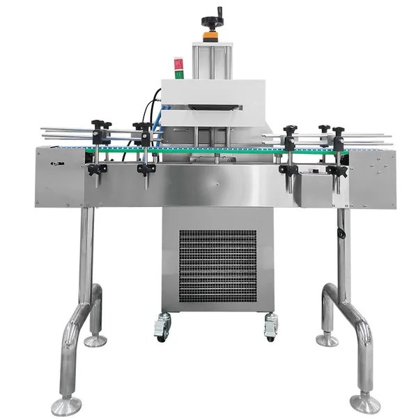
Figure 1. SED water-cooled aluminum foil induction sealing machine for capped bottles.
Why Induction Sealing Defects Occur
Induction sealing defects rarely begin with a single bad power setting. A foil liner bonds only when the capped package supplies uniform pressure at the bottle land, the liner's sealant matches the container material, and the induction system delivers enough energy for the available exposure time. Start with cap application torque, liner orientation and fit, and the bottle neck finish. Then verify sealing-head position, conveyor speed and power as a controlled combination. Do not judge the result while the liner is still hot: allow the package to cool under the approved procedure, then confirm the bond with a defined peel or leak test.
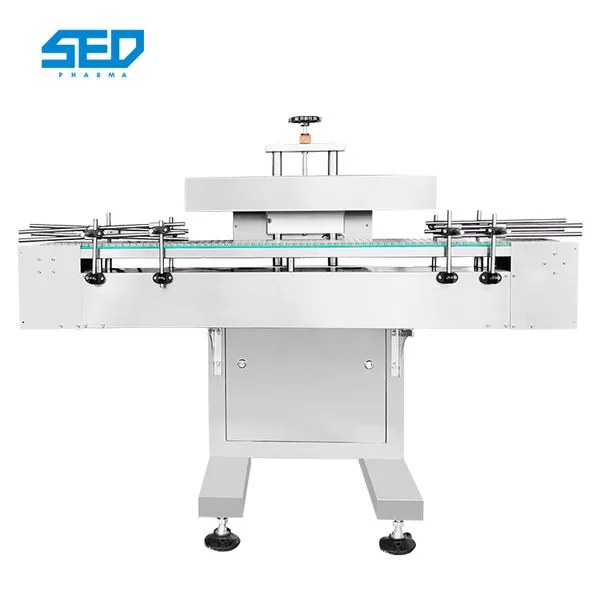
Figure 2. SED aluminum foil induction sealing machine showing the conveyor and sealing-head arrangement.
Read the Defect Before Changing the Machine
Separate the symptom from the suspected cause. A no-seal condition, a partial crescent, an easy-peel bond and a scorched liner can overlap in appearance, yet they require different confirmation tests. Record the bottle position, cap condition, liner face, head setting, actual conveyor speed and time since sealing for each sample. Photograph the liner and land after opening. This evidence prevents a power adjustment from masking a torque or component problem.
- No seal across the full land: confirm that a foil liner is present, correctly oriented and compatible before evaluating energy delivery.
- Partial or crescent seal: inspect cap seating, torque variation, bottle finish flatness, head parallelism and bottle centering.
- Weak seal after cooling: compare representative samples at the approved test time; check marginal pressure, liner-to-resin mismatch or low energy input.
- Scorching, pinholes or neck distortion: stop increasing power; inspect dwell time, bottle backup, head gap and excess heat exposure.
Cause-Test-Action Diagnostic Table
| Possible cause | Confirmation test | Corrective action |
|---|---|---|
| Low or variable cap application torque | Measure application/removal torque on a planned sample; inspect cross-threading and cap seating | Correct capper setup and handling; establish the approved torque window with the package supplier and validation team |
| Liner missing, inverted, oversized, undersized or not retained flat | Open unsealed controls; verify liner construction, sealing face, diameter and seating in the closure | Quarantine mixed components; correct liner/closure specification or feeding before changing sealer power |
| Bottle land uneven, flashed, damaged or contaminated | Inspect and compare the full sealing land under good light; use flatness or dimensional checks specified for the package | Clean the process source; segregate damaged containers; escalate mold/finish variation to the container supplier |
| Sealing head too high, tilted or off-center | Check the approved head-to-cap gap, parallelism and bottle path with power isolated | Reposition the head and guides; document the format setting and requalify if required |
| Energy too low for conveyor speed | Run controlled samples at the fixed production speed, changing one approved setting at a time | Identify the minimum complete seal and the upper limit before damage; set the validated operating range |
| Energy too high or dwell too long | Look for scorching, backing adhesion, pinholes, softened land or defects during line slowdowns | Reduce exposure within the approved study; interlock or manage startup, stops and bottle backups |
| Product contacts the liner or wets the land | Inspect fill height, splash, foam and residue before capping; compare filled and empty controls if permitted | Correct filling/handling and cleaning; assess product-liner compatibility with the supplier |
| Seal disturbed before cooling | Record cooling time and when the cap is removed, retorqued or leak-tested | Standardize cooling and test timing; avoid retorquing unless the package procedure specifically requires it |
Troubleshooting Sequence: Mechanical Before Electrical
- Contain and document. Separate suspect packages and preserve the settings, component lots, defect photos and test timing. Follow the site's deviation and material-control procedures.
- Confirm the symptom. Let representative samples cool for the specified interval. Use the approved leak, vacuum, squeeze, dye, peel or other package-integrity method. A visual ring alone is not proof of seal integrity.
- Verify the component stack. Confirm the bottle resin, neck-finish specification, closure, liner construction, sealant face and component lot. The foil must face the correct direction and the heat-seal layer must be intended for the container material and product.
- Measure torque and seating. Check application and removal torque with a calibrated method defined by the closure system. Trend the distribution, not only the average. Look for cross-threading, stripped threads, cocked caps and closure-to-shoulder interference.
- Inspect the sealing land. Check flatness, flash, ridges, parting lines, narrow contact area, moisture and product residue around the full circumference. Rotate suspect bottles to learn whether the defect follows the bottle or remains fixed relative to the machine.
- Check head geometry and bottle presentation. With energy isolated, verify the approved air gap, head level, centering, guide-rail stability and bottle height. A tilted head can deliver uneven heating even when displayed power is unchanged.
- Challenge power and speed as a pair. At the intended production speed, change only one approved variable per trial. Bracket a lower boundary that produces a complete cooled seal and an upper boundary before scorching, pinholes, backing adhesion or container damage. Exact values depend on the sealer, coil, foil area, liner, bottle, product and validation method.
- Confirm the operating window. Repeat across representative component lots, filled conditions, startup/stop scenarios and expected line-speed variation. Record the final settings and acceptance criteria through change control. SED Pharma can review defect photos, component details and current line settings when equipment or line integration is part of the investigation.
Torque: Pressure Must Be Uniform, Not Merely High
Cap torque creates the contact pressure that holds the liner against the bottle land during heating and early cooling. Too little torque can leave gaps; excessive torque can distort the neck, strip threads or interfere with liner behavior. Because torque depends on closure diameter, thread design, liner compressibility, bottle rigidity, capper type, application speed and time after capping, a generic torque number is not a defensible setting.
Measure torque close to the relevant process point and with a defined method. A stable average can conceal a wide distribution, so review individual results and defect correlation. If increasing torque appears to fix the leak, still inspect the finish and component fit: extra force may temporarily compensate for an uneven land or poorly retained liner without removing the root cause.
Use a controlled torque study rather than comparing one good bottle with one failure. Sample bottles across the capper cycle, after a magazine refill and after a controlled restart. Record application or removal torque using the site's approved method, then map each result to cap seating, liner position and the cooled seal result. If failures cluster at one capping head or one time interval, investigate that mechanical source before changing the induction sealer. Torque limits and measurement timing must come from the qualified closure system, component supplier and validated packaging procedure; this article does not provide a universal numerical target.
Liners and Bottle Necks: Check Compatibility and Contact
An induction liner is a material system, not simply a foil disk. Its seal layer must bond to the intended container resin, and its backing or wax construction must behave correctly for the closure design. Confirm the supplier's specification for the bottle, product and storage conditions. A liner can heat visibly yet fail to bond if the sealing face is wrong or if product chemistry attacks the structure.
The disk must remain flat and centered in the cap. Oversize liners can fold into threads; undersize liners reduce contact area; rigid liners may not conform to finish variation. On the bottle, flash, a saddle-shaped land, dents, treatment residue, moisture or product contamination can create a leak path. Compare components across lots and inspect known-good controls before altering electrical settings.
A useful isolation test compares known-good bottle, closure and liner components with the suspect lot while keeping the capping and sealing recipe unchanged. Change only one component family at a time and preserve lot identity. Rotate marked suspect bottles before they enter the sealer: if the weak area rotates with the bottle, the evidence points toward the land, seating or contamination; if the weak area stays fixed relative to the conveyor, investigate head alignment, bottle guidance or field distribution. Any component substitution used for diagnosis must be authorized and must not be released as saleable product unless the site procedure permits it.
Power, Line Speed and Head Gap: Build a Window
Displayed power is only one part of delivered heat. Conveyor speed changes exposure time, while coil design, head gap, alignment, cap diameter, foil area and bottle position affect coupling. Product close to the liner may also act as a heat sink. For that reason, a power percentage from another machine or bottle format is not transferable.
Establish the window at the intended line speed with representative filled packages. Approach the minimum energy that gives a complete seal after cooling, then identify the upper boundary before heat damage. Evaluate line ramps, short stops and bottle backups because they can increase dwell. Changes that affect validated package integrity should follow the site's SOP, risk assessment, validation and change-control requirements.
Design the trial as a small controlled matrix within authorized limits. Hold capper setup, component lots, fill condition and head position constant. At a fixed conveyor speed, evaluate approved power steps and test seals only after the defined cooling interval. Then repeat the selected power condition at the permitted low, nominal and high line speeds. Record actual speed, displayed power, head gap, bottle presentation, cooling time and integrity result for every condition. The acceptable setting is a range that survives representative variation, not the single point that produces the strongest-looking foil.
Include abnormal but expected operating events in confirmation. A short stop can keep a package beneath the head longer than normal, while a rapid restart can change spacing and presentation. Verify the machine's stop logic, bottle backup controls and reject or alarm response using the approved procedure. Never defeat guarding, interlocks or energy isolation to observe the induction head.
Supporting source: SED water-cooled aluminum foil induction sealing machine working principle
How to Confirm the Fix
A corrected setting is not confirmed by a single attractive foil. Define acceptance before the trial, sample across time and positions, and use a test suited to the package and product risk. Record cooling time because hot seals can be disturbed or misread. When relevant, retain samples for delayed inspection because chemical attack or stress may not appear immediately.
- Compare defect rate and location before and after the isolated change, using the same sample plan and test method.
- Verify both seal bond and package function: leakage, cap removal, liner separation, container damage and product contact as applicable.
- Repeat with representative bottle, cap and liner lots, and confirm restart or slowdown conditions.
- Update approved recipes, setup sheets and training only after quality and validation review.
Define the acceptance plan before running confirmation samples. Specify component lots, sample positions, production speeds, cooling interval, package-integrity method, restart conditions and the treatment of rejected units. Where the package has a validated test method, use its established quantities and limits instead of inventing a new threshold for the investigation. Retain before-and-after photographs, torque records and machine settings with the deviation or maintenance record so a recurring defect can be compared against the same evidence set.
Conclusion
Reliable control of induction sealing defects begins with pressure and package compatibility, then moves to energy delivery. Measure cap torque and seating, verify the liner and bottle neck finish, check head geometry, and only then tune power against conveyor speed. Confirm every change after cooling with a defined leak or peel method. This sequence prevents an electrical adjustment from hiding a mechanical or material fault and produces an operating window that can be defended across routine production.
Need help isolating a recurring seal failure?
Send SED Pharma the bottle and cap specifications, liner construction, defect photos, torque records, head gap, conveyor speed, power setting and test method for an initial technical review.